What Future Trends Can We Expect in Current Sensing?
Introduction
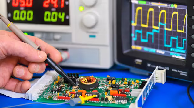
For any electrical control system, input signals of both voltage and current are critical for the system to operate according to the intended design and in a safe manner. In power supplies and motor drives, as an example, current is measured for control (like peak-current mode or average-current mode control in power converters), protection (like short-circuit overcurrent protection), and data-logging purposes.
While measuring voltage is often simple in that it can be measured at many points accurately, can interface with most controllers directly, and can be done without impacting the system, measuring current is usually not so straightforward. As we learn in university, whenever we measure current, we often must “insert” a foreign sense element into the system to serve the purpose of measurement. To do this in a way that the measurement is accurate, requires little PCB space and few components, adds little cost and preserves the original system performance becomes the designer’s challenge. Most existing approaches require careful tradeoffs. Some motor applications even push to move toward complicated “sensorless” control to save that appreciable sensor cost and PCB space – and be able to operate in a wide ambient temperature environment or challenging ionization/magnetic field environment. These approaches still face challenges in timing, delays, and accuracy operating from software models and complicated control-loop algorithms. A new, highly integrated, “lossless”, and localized approach to current sensing will be demonstrated in this article that solves many of those challenges. Let’s start, firstly, with some background on the traditional approaches.
Shunt Resistors
One of the simplest methods to measure current is to add a shunt series resistor into the current path of interest, and then measure the voltage across it as a representation of that current, knowing the relationship of Voltage = Current * Resistance, (V = I*R), and assuming a stable, or linear, resistance.
This popular method is simple and accurate. It can be used for DC or AC current measurements and is flexible for a variety of applications. While not intrinsically isolated, some vendors offer isolated amplifiers or isolated ADCs for this approach. Vendors like Texas Instruments, Skyworks, Broadcom, Allegro, ON Semi, and many others offer solutions in this area. However, this current sense method does introduce an additional power loss element, especially at high current, which can be a severe limiting factor in high-power, high-efficiency systems. It also adds parasitic source inductance in the power path and gate loop of low-side switches, where it is most unwanted, causing delayed turn-off and voltage spikes. These resistors are not standard off-the-shelf components either. To carry the full rated load current, and meet typical accuracy of 1% resistance over temperature, very low RDS(ON) FETs and highly optimized shunt resistors must be used. To avoid heavy losses, a variety of low- RDS(ON) FETS with large thermal package options are available from current sense resistor providers including vendors such as Vishay, Ohmite, Bourns, Susumu, and others.
Pushing for low power loss, and low voltage drop across these resistors then requires excellent op amps to gain and condition the signal properly for use. Further, to meet efficiency and thermal requirements with this added series resistance, designers must also use lower RDS(ON) and more expensive components to reduce the other power loss in the power path to compensate. (For example, using even lower RDS(ON) Power MOSFETs.)
What started out as a simple measurement now requires multiple additional components that need to be carefully selected, designed, and powered properly, while also consuming PCB space and cost.
Current Transformers
Another common method of current measurement that simplifies the system when isolation is needed or with high power, high efficiency systems is using a current transformer (CT). Gain can be accomplished with the transformer turns ratio, isolation is built-in, and bi-directional current can also be measured. Further, no bias supply is needed for the CT, regardless of whether it is used in high-side (floating reference) or low-side (ground-referenced) configuration. The downsides, though, are that DC current cannot be measured, there may be duty-cycle limitations to prevent transformer saturation, and these CTs are also usually large components – most typically toroids like those in below, which may limit their adoption in high-density systems. LEM, Wurth, Renco, and many other magnetics vendors offer dedicated products focused on this approach.
Hall-Effect Sensors:
For applications at still higher power, or when DC current information is required, designers often look at sensing methods that minimize the lossy pass elements being added to the system (like shunt resistors or CT primary windings), and instead rely on measuring field effects of the system. Considered “non-contact”, “lossless” sensors, methods like Hall-Effect current sensors operate under the principle that for a given conductor (like a copper trace on a PCB) with current flowing through it, a proportional magnetic field is created around the current-carrying conductor. By measuring such a magnetic field, information on the value of the current that produced it can be obtained. The sensing element often has the PCB copper flow through the sensing element package, and some others place the sensor above the copper trace and sense through proximity only. 100’s and 1000’s of amps can be measured with low loss because resistance and inductance is not being added to the system, but the method becomes inaccurate at low current, can be made inaccurate by external fields or mechanical orientation, and often requires a zero-current offset and a concentrator to magnify the signal for a narrow range of current of interest. Further, a dedicated bias power supply is required for such a measurement IC. Allegro, Melexis, Koshin, and many other vendors offer products focused on this approach.
Anisotropic Magneto-Resistive (AMR) Sensing:
Capable of sensing both AC and DC signals and offering a high bandwidth solution up to 1.5MHz, with an isolated output, the AMR IC operates by having the current flow into the device through a low resistance “U-bend” in the leadframe where it generates either a forward or reverse magnetic field that is sensed by two differential current sensors. This approach is attractive in that it is fairly compact, resistant to external fields and noise, and has low offset error while also responding very quickly (<300ns) which allows it to be used in high-frequency control applications such as power supplies and motor drives using wide bandgap semiconductors such as GaN and SiC.
The Future: Introducing “GaNSense™” Technology:
With the continued push for higher efficiency, gallium nitride (GaN) based power converters have become more and more popular in the market. Further, with high levels of integration used in monolithic GaN Power ICs, power converters could be pushed to higher frequency with a minimal number of external components, allowing for much smaller systems. Ground-breaking products such as the latest fast mobile-phone chargers have been able to achieve power densities even three times higher than best-in-class previous solutions. But the efforts to extract all the capability out of GaN continued, and in late 2021, GaNSense technology with still further integration and expanded features was released.
Simplest form GaNSense is lossless current sensing in-circuit, removing the shunt current-sense resistor and its associated headaches and improving the overall efficiency of the system with lower total series resistance, while also increasing robustness with fast, internal, 30-100ns short-circuit protection. This approach is a “localized” approach in that it is sensed and acted upon locally to the current and power elements of interest. Localized control and response time allows this method to be fast and effective, while also minimizing corruption of the control signals from system noise, long traces, etc. compared to other methods. In this way, it becomes possible to use this method not only for over-current failsafe and short-circuit protection, but also cycle-by-cycle current limit and current-mode control and regulation. This self-governing power block may indeed represent the future of powerstage sensing and protection, allowing for higher reliability, pushing the limits of performance, and freeing the main system controller to focus on more complicated control algorithms and responsibilities.
Within the CS block the main power FET device is connected to the common drain and gate connections. For simplicity’s sake, we will show the sources connected commonly as well. By using well-matched devices and using a high on-resistance sense-FET (maybe >10001500 times higher RDS(ON) than the main power FET), a small portion of the load current branches off to the sense FET and can be measured accurately through a variety of techniques. RDS(ON) and temperate affects are also cancelled out naturally. Because of the tight matching the current is based on the ratio of the resistances of the devices only. As the sense FET is much higher RDS(ON) than the main power FET the loss from this approach is negligible, especially compared to alternatives like shunt current sense resistors in the main power path. The current limit is still adjustable and programmable, with the Current Sense (CS) pin and programming resistor.
All these benefits translate to system improvements. An example below in Figure 5 can be seen whereby designers leveraged GaNSense technology to achieve an AC/DC 120W mobile phone charger that was 70% smaller, 65% lighter, and almost 6% more efficient than the previous production solution.
0 Comments