The Functions of Voltage Sensors and Their Uses
A sensor is typically an electrical device that detects and reacts to a certain signal, such as an optical or electrical signal. Sensor technology implementation in voltage or current has emerged as a superior choice for voltage and current measurement methods. The key benefits of sensors over traditional measurement techniques are their reduced size and weight, high precision, safety, nonsaturability, and environmental friendliness. It is possible to combine the measurements of voltage and current into a single, small, solid device. An overview of the voltage sensor's operation is included in this article.
A voltage sensor: what is it?
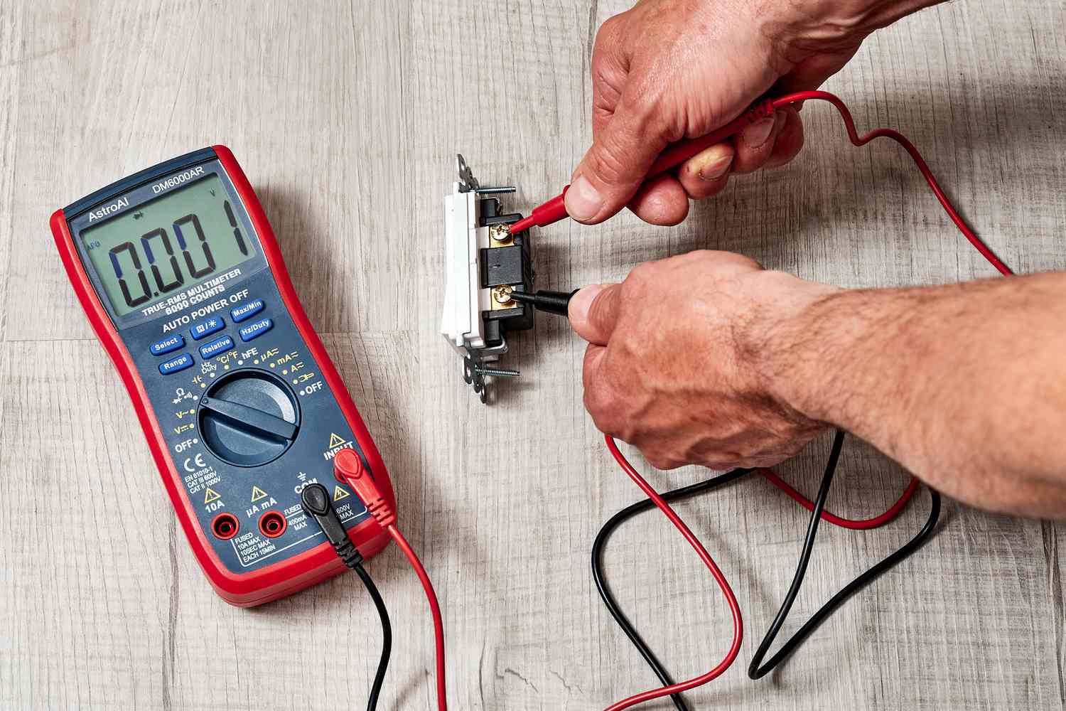
The voltage supply is monitored, calculated, and determined using this sensor. The AC or DC voltage level can be ascertained via this sensor. This sensor's output can be switches, analog voltage signals, current signals, audio signals, etc., while its input can be voltage. While some sensors can provide outputs like AM (Amplitude Modulation), PWM (Pulse Width Modulation), or FM (Frequency Modulation), others can only produce sine or pulse waveforms. The voltage divider may have an impact on these sensors' measurements.
There are input and output on this sensor. Positive and negative pins are the two major components of the input side. The device's two pins can be linked to the sensor's positive and negative pins. The positive and negative pins of the gadget can be linked to the sensor's positive and negative pins. This sensor's output primarily consists of analog o/p data, ground (GND), and supply voltage (Vcc).
Voltage Sensor Types
Resistive and capacitive sensors are the two categories into which these sensors fall.
1) Sensor of the Resistive Type
Two circuits, such as a voltage divider and bridge circuit, are the primary components of this sensor. The circuit's resistor serves as a sensing component. To create a voltage divider circuit, the voltage can be divided into two resistors, such as a reference voltage and a variable resistor. This circuit is supplied with voltage. The circuit's resistance can determine the output voltage. in order to enhance the voltage change.
Four resistors can be used to create the bridge circuit.The voltage detector device can be applied to one of these resistors. It is possible to directly observe the voltage change. Not only may the difference within the voltage divider circuit be amplified, but this difference alone can be amplified.
2) Sensor of the Capacitor Type
An insulator and two conductors in the middle make up this kind of sensor. There will be current flowing through the capacitor because it is powered by 5 volts. This may cause the capacitor's electrons to repel one another. The voltage is indicated by the capacitance difference, and the capacitor can be linked in series.
Uses
The following are some of the uses for this sensor.
Identification of a power outage
Safety switching for load detection
regulating the temperature
Managing the demand for power
Finding the fault
Temperature variation in load measurement
This brings us to the topic of voltage sensors, which are useful for determining the voltage range in any kind of device. It determines a device's electrical charge. This sensor's operation is mostly based on the capacitive or resistive principle.


0 Comments