Current Sensors: Types, Key Parameters, Performance Comparison
Introduction Current sensors are critical components in a wide range of electrical and electronic systems, ensuring that equipment and gadgets operate safely and efficiently. We will examine current sensors in this article, including their kinds, variables to consider when choosing a current sensor, performance comparison, and applications.
What is a Current Sensor?
A current sensor detects and measures the electric current passing through a conductor. It turns the current into a quantifiable output, such as a voltage, current, or digital signal, which may be utilised in a variety of applications for monitoring, control, or protection.
Types of Current Sensors and Their Advantages and Disadvantages We may categorize current sensors based on the fundamental physical concept that underpins their construction. These current sensor concepts include Ohm's Law, Faraday's Law of Induction, Magnetic Field, and Optical Sensing. With this classification, we will now cover the many types of common current sensors.
Ohm’s Law-based Current Sensing
Ohm's law states that voltage appears proportionate to the current supplied across a resistive element. Various sensors, including the frequently used shunt resistors and copper lines, have been devised using this fundamental approach.
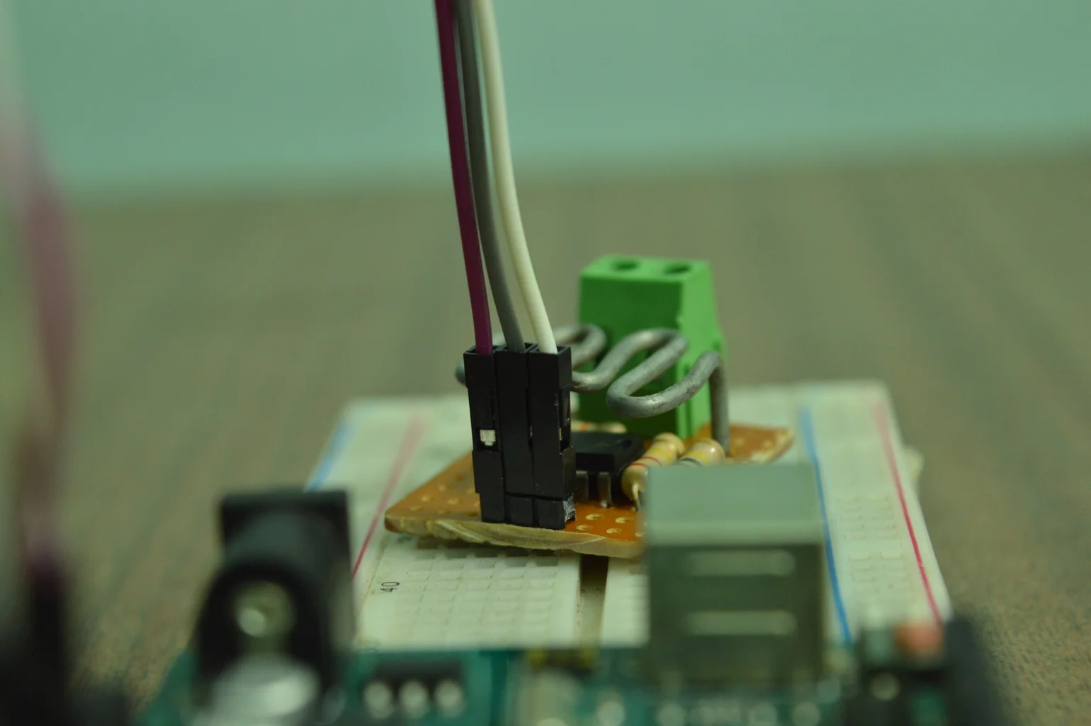
Shunt Resistor:
These are precision resistors with low resistance that are connected in series with the current carrying wire. The voltage drop across the shunt resistor is proportional to the current flowing through it, and this voltage may be measured to find out how much current is passing through it. Shunt resistors are capable of measuring both AC and DC currents. Because the shunt resistor is in the current conducting path, it can cause considerable power loss that grows with the square of the current. In high current applications, this power loss may limit the usage of shunt resistors. Coaxial shunts have been widely used in a variety of applications requiring quick rise-time transient currents and large amplitudes. However, due to their tiny size and cheap cost, low-cost surface mounted devices (SMDs) are preferred by highly integrated electronic gadgets.
Copper Trace:
It is also feasible to use the intrinsic resistance of a conducting element in the circuit instead of a specific shunt resistor. However, because a copper line has a low resistance and hence a low voltage drop, a high gain amplifier is required to obtain a useful signal.depicts a typical application of a shunt resistor for current sensing. The produced voltage is then amplified to take use of the ADC's entire measuring range before being supplied into a digital controller for processing. A significant drawback of this sort of current sensor is the intrinsic electrical connection that exists between the current to be measured and the sensing circuit. Electrical isolation can be obtained by utilizing an isolation amplifier, which raises the sensor's price. It can also reduce the bandwidth, accuracy, and thermal drift of the original current sensing technology. As a result, in situations where isolation is critical, current sensing devices based on physical principles with built-in electrical isolation are preferable.
Faraday’s Law Of Induction-Based Current Sensing
Faraday's Law of Induction, which says that the total electromotive force (emf) generated in a closed circuit is proportionate to the time rate of change of the total magnetic flux linking the circuit, is widely used in current sensing devices. Two common Faraday's law-based sensing devices are current transformers (CTs) and Rogowski coils. When electrical isolation is required for safety reasons, these sensors automatically provide the necessary isolation between the current to be measured and the output signal. This makes present detecting equipment valuable.
Current Transformers (CTs):
The CT has a main winding (usually single-looped), a core, and a secondary winding. It is an effective high AC current measuring sensor. As a result, a large main current can be transformed into a smaller secondary current. This gadget doesn't require any additional driving circuitry because it is passive. Another important feature is that it can monitor very high current while using very little electricity. The ferrite material used in the core, however, can get saturated by a very high primary current or a substantial DC component in the current, causing the signal to be distorted. Another problem is that the core will have hysteresis once it has been magnetic, which will lower accuracy unless it is demagnetized once again. Furthermore, because the fundamental idea relies on the detection of a flux change, which is proportional to a current change, they cannot detect DC currents in standard form.Illustrates how CT operates. Depending on the turns ratio, the change in the main current Ip is reflected on the secondary side as Is, which may be utilized for sensing. A shunt resistor that generates output voltage proportionate to the primary current can be used to monitor the output current. This provides isolation, minimal losses, a straightforward operating principle, and a voltage output that doesn't require extra amplification for current sensors. An analog-to-digital converter (ADC) may be able to sample the output voltage directly. The primary current drop ratio is shown by the CT ratio. A current transformer's accuracy is gauged by its current transformer accuracy class, sometimes referred to as current transformer class or CT class. Based on their accuracy class, CTs are divided into two categories: metering accuracy CTs and relaying accuracy CTs. Metering Accuracy CTs are designed to be exceedingly accurate at all current ratings, even at very low current. They are evaluated for particular common loads. Due to its high level of precision, utility companies routinely utilize these CTs to assess usage for billing purposes. Relaying accuracy CTs are less accurate than metering accuracy CTs. They are designed to work with the minimal level of precision needed for equipment protection. Due to their low cost and ability to create an output signal that is right away compatible with an analog-to-digital converter, current transformers are frequently utilized in power conversion applications. They also play a significant role in power distribution networks operating at 50/60 Hz line frequencies.
Rogowski Coils:
These air-core coils are flexible and are wound around a conductor. A voltage in the conductor that is proportional to the rate of change of the current is induced by the changing magnetic field caused by the current in the conductor Ip. The main use of Rogowski coils is to measure AC currents, especially in high-frequency applications.The Rogowski coil has a reduced sensitivity since the current transformer is unable to employ a magnetic core with high permeability. The Rogowski coil stands out since it is fundamentally linear and doesn't show saturation. Rogowski coils can be used to detect currents in power distribution systems, short-circuit testing systems, electromagnetic launchers, slip-ring induction motors, and lightning test facilities. Comparable to modern transformers in price.
Magnetic-Field Sensors for Current Sensing
It is difficult to detect currents that generate static magnetic fields using Faraday's law of induction. On the other hand, magnetic field sensors can identify both static and moving magnetic fields. They present themselves as a desirable alternate choice for current sensing.
Hall-Effect Sensors
These sensors are based on the Hall effect, which states that when a magnetic field is applied across the cross-section of a current carrying conductor, a voltage difference is formed across the conductor (see Figure 4). We can determine the direction of the electromotive force (emf) that is formed orthogonal to the current and magnetic field using the Fleming left-hand rule. The amplitude and relative angle of the current and magnetic field determine the resultant vector voltage, which is proportional to the Hall constant. The magnetic field is created by the current to be detected, which creates a magnetic field that provides voltage that may be analysed.
To make the output usable in most applications, signal conditioning is required. Signal conditioning electronics often require an amplifier stage as well as temperature correction. A differential amplifier with these properties may be simply combined with the Hall element using standard bipolar transistor technology. Temperature compensation is also simple to implement. Figure 5 shows a typical design of a Hall-effect current sensor.
Fluxgate Sensors
The basic fluxgate sensors make use of the nonlinear connection between the magnetic field, H, and magnetic flux density, B, within a magnetic material, resulting in a change in the material's permeability.On the magnetic core, two windings are installed: the excitation winding and the pickup winding. The excitation winding is coupled to a sinusoidal current source, which creates a magnetic field of excitation. As a result, voltage is generated in the pickup winding, which may then be used for sensing. Given that the external field is minimal in comparison to the excitation field, the peak in output voltage is proportional to the external field and may be used to quantify it.
Due to their high cost and limited area, isolated fluxgate sensors have proved commercially useful primarily in high precision applications. Because of their high accuracy, fluxgates are employed in calibration systems, diagnosis systems, laboratory equipment, and medical systems.
Magneto-Resistive (MR) Sensors
Figure 7 shows a magneto-resistor which is a two-terminal device whose resistance varies in response to an applied magnetic field. The magnetic field's influence on material resistance is referred to as the MR effect. Using the MR effect, changes in the current to be detected cause variations in the magnetic field, which are reflected on the voltage that may then be analyzed.These resistors are frequently used in a bridge design to compensate for thermal drift. Current sensors may be made using the MR effect. Anisotropic MagnetoResistance (AMR), Giant Magneto Resistance (GMR), Giant Magneto Impedance (GMI), and Tunnel MagnetoResistance (TMR) are examples of common forms.
Configurations of Magnetic Field-Based Current Sensors
These magnetic field-based current sensors are widely utilized in both closed-loop and open-loop applications. The magnetic field sensor's output voltage is employed as an error signal in a closed-loop setup to push a current via a second transformer winding. This current generates a magnetic field, which compensates for the flux inside the magnetic core and forces it to zero. Under ideal conditions, the secondary current is proportional to the primary current ip.
With open-loop sensors, temperature drift or other non-linearities in the sensor will result in inaccuracies. On the contrary, closed-loop sensors enhance accuracy and saturation performance. The sensor configuration used is determined by the specific application and needs. Due to their cheap cost, compactness, and power needs, open-loop current sensors are quite widespread. Closed-loop current sensors are recommended in applications that require great accuracy and resistance to saturation, particularly in environments with broad temperature changes or electrical noise.
Fiber-Optic Current Sensors
To create current sensors, the Faraday magneto-optic effect can be used. The Faraday effect causes polarisation rotation that is proportionate to the magnetic field projection along the light transmission route. Most optically transparent dielectric materials exhibit this phenomenon when subjected to magnetic fields. Figure 10 depicts how a magnetic field, maybe created by a detected current, might cause polarization owing to Faraday's effect.
0 Comments